Chainforcer Lowpoly Modeling Stages
Posted on 2016-03-11 in projects
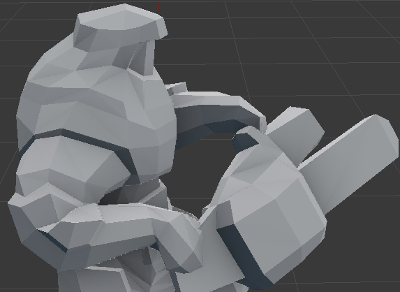
While working on this model I saved several in between backups. These screenshots show the stages the model went through.
Concept / Viewport Background
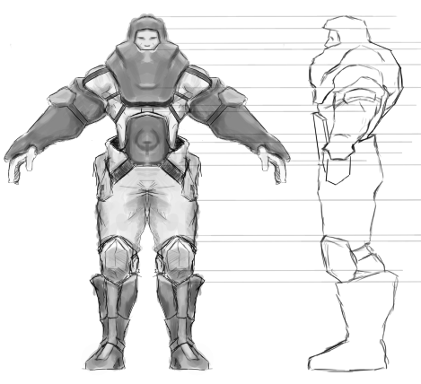
The basic character concept and also essential viewport backgrounds that will define the form. Both views contain different information on one axis but the same on the vertical axis. To use this as viewport backgrounds I made sure the landmarks on the vertical axis are on the same height. That's why there are these lines.
Blender's Skin Modifier
The basic form is created using a combination of blender modifiers (mirror, skin, subdivison). You can see a thin line inside the model. Thats what's manually defined. The actual hull is what the skinmodifier does. It creates a hull mesh around verts and edges. Geometry will be added when verts move apart. The volume increases when verts are scaled. The geometry isn't optimal but I think it still saves time since I only had to define 13 vertices to get this basic shape.
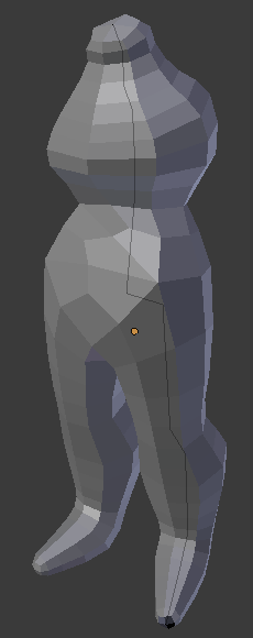
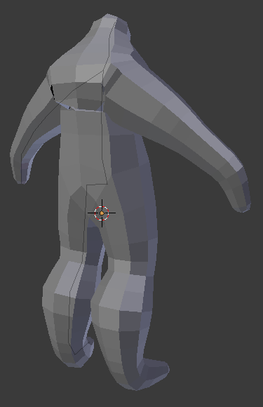
Refining
- Started with the boots by moving the verts from all angles so they align with the background images.
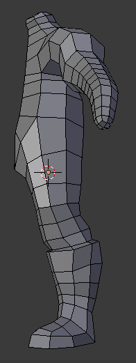
- Removed some unneccessary edges to have about even poly density.
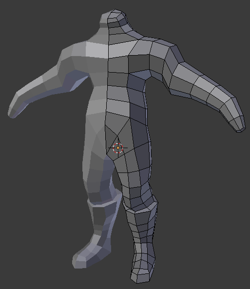
- I noticed some triangles in the geometry and removed them by adding edge loops.
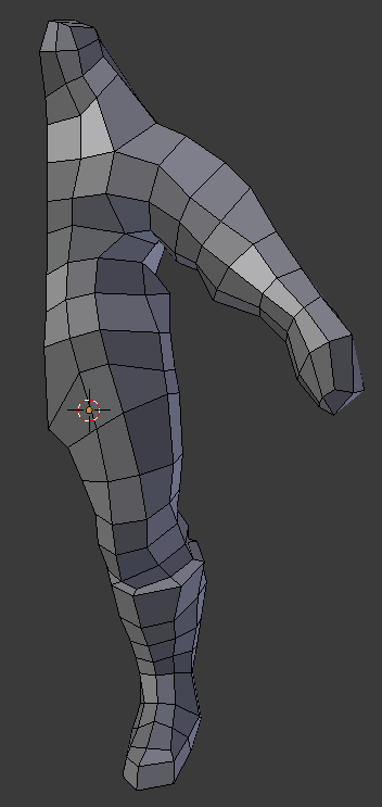
- Gradually touching all vertices to define the form.
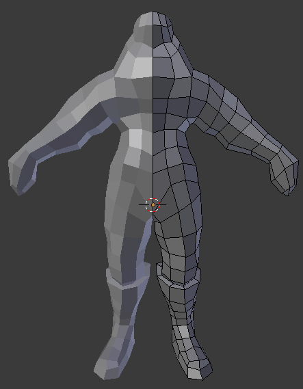
- Some more form definiton on the hips and head.
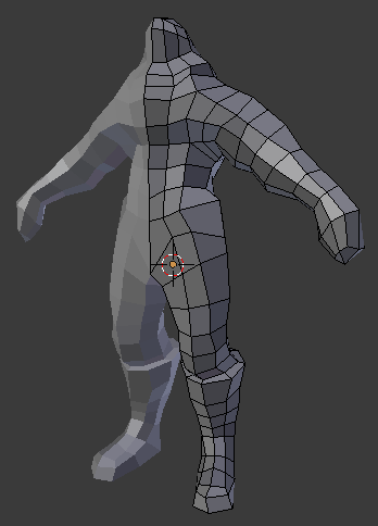
- Extruded the belly plate and arm ammo packs. Also defined the shoulder/glove transition.
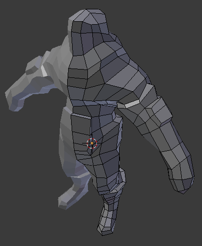
- Create the leg ammo packs and face indentation using the extrude tool.
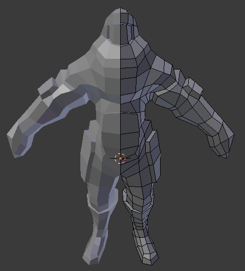
Done
- Finally removed edgeloops that don't add much to the form to reduce polycount.
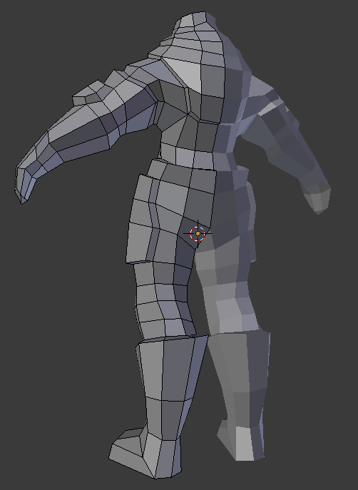
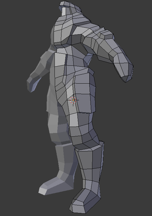
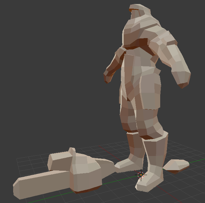
- Added a weapon (chainsaw-grenade-launcher) and a "muzzle flash"
UV Mapping
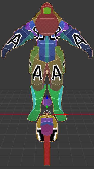
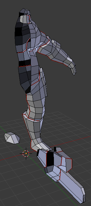
- This is how the model was cut for uv mapping. The red edges mark uv seams.
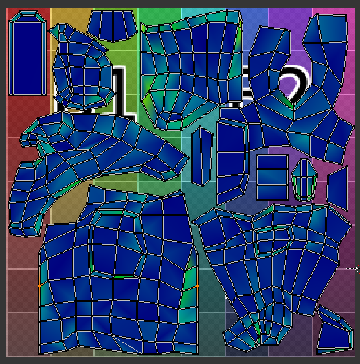
- Here the resulting UV map. I aligned some of the seam vertices to make hiding them easier later. Unwrapping option was set to "conformal" most of the time.
